Nowadays, CAD software has become an indispensable tool in the fields of design and manufacturing. Whether you’re involved in engineering design, architectural design, or other manufacturing-related work, you’ll find a file format that frequently appears in your industry: DXF.
This is a file format developed based on CAD tools. Do you know what it’s used for? Are you familiar with how to create DXF files? If these questions pose a challenge, this article is here to help you overcome it. Take a few minutes to read through this article. We’ll not only introduce you to the uses and benefits of DXF but also delve into two different methods of creating DXF files, empowering you to handle various needs in the design and manufacturing process more flexibly.
What Is a DXF File
In the early days of CAD applications, there were interoperability issues between different software. As each software had its own unique file format, data exchange became a challenge. To address this problem, in the 1980s, AutoCAD developed the DXF file format.
It’s an open, ASCII text-based format for storing 2D and 3D graphic data such as lines, polygons, and text. Its open standardized format and flexibility enable designers, engineers, and manufacturers to share, edit, and convert design data across different platforms without compromising the quality of graphic data, which is crucial in diverse workflows.
To open DXF files, there are typically two methods: using a DXF viewer or using CAD software. If you have an urgent need to view the contents of a DXF file, you can use a DXF viewer. However, the drawback of such software is the inability to edit or modify the file. On the other hand, CAD software offers much more flexibility. It provides numerous advanced features, allowing users not only to view but also to edit, modify, and create DXF files according to their design requirements.

How to Create a DXF File with ZWCAD
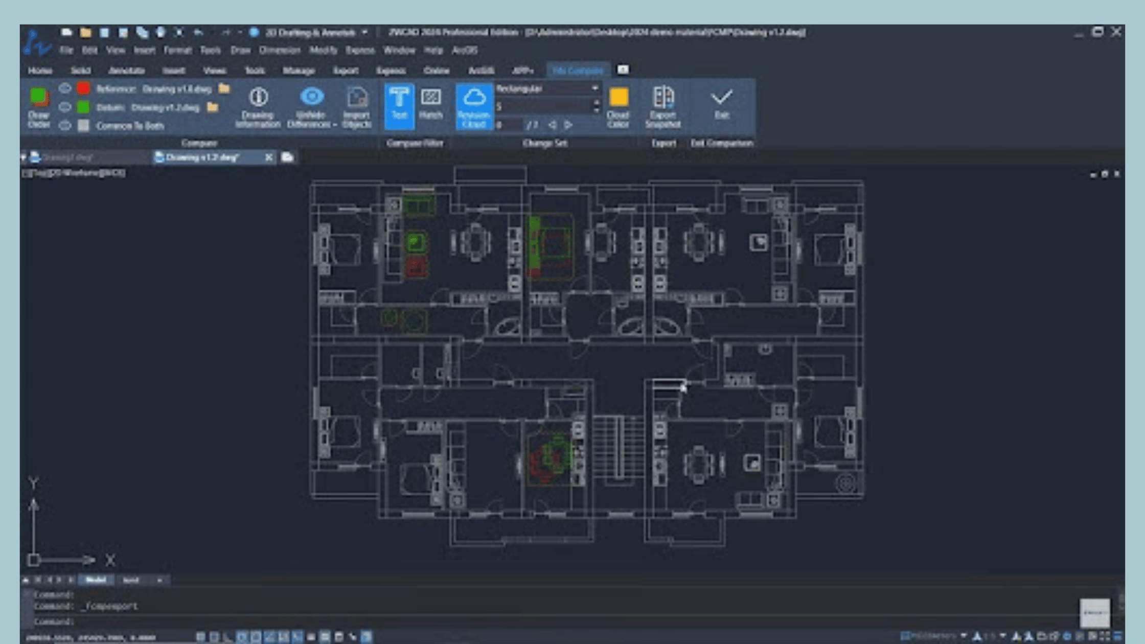
The first method is to create a DXF file by using ZWCAD. If you’ve been in the design industry, you’re likely familiar with this name. It’s a powerful CAD software with comprehensive 2D drafting and 3D modeling capabilities. ZWCAD supports a wide range of CAD file formats, including DXF, DWG, DWT, DWS, PDF, etc., making it a capable DXF viewer and DXF editor as well. With ZWCAD, you can easily view the graphics content within DXF files and perform editing, modifications, and additions of new graphic elements, before saving them in DXF format or other supported formats.
ZWCAD is lightweight and requires only minimal specifications of 2GB RAM and a 1GB graphics card. Additionally, thanks to its hardware acceleration and multi-threading parallel computing optimization, it operates swiftly even when handling large DXF files, with no lag or slowdowns. Whether as a CAD tool or a DXF editor, ZWCAD proves to be highly efficient.
Now let’s take a look at the specific steps to create a DXF file with ZWCAD:
Step 1. Complete your 2D design in ZWCAD.
Step 2. In the menu bar at the top left corner, select the “File” option, then click “Save as” from the dropdown menu.
Step 3. Choose “DXF (*.dxf)” format in the “Save as type” section.
Step 4. Finally, name your file and select the save path, then click “Save” to export your drawing in DXF file format.
How to Create a DXF File for Laser Cutter
The second method involves utilizing the production process of laser cutting to create DXF files. This method is feasible because DXF is one of the preferred input file formats for laser-cutting software. Therefore, this process can be used to create DXF files, although the operation may be a bit complex. The specific steps are as follows.
Step 1. Edit an Image for DXF File
Firstly, choose an image with clear outlines, preferably black and white. Then, open it using the image editing software MS Paint. Remove unnecessary details to make the outline of the image clearer and more concise before saving it.
Step 2. Import Into Inkscape and Trace Bitmap
Import the edited image into vector graphic editing software Inkscape. Then, select the image and click “Path” from the top menu. Choose the “Trace Bitmap” function to convert the image into vector paths. You can adjust the value of the threshold in the top box to define where the edge of the lines in the image is, and then click “OK”.
Step 3. Sketch the Bases or Suspension Holes
Then, use shortcuts and drawing tools to sketch the bases or suspension holes. These bases or suspension holes will be used to secure or hang your design, so it’s important to ensure their positions and dimensions are appropriate.
Step 4. Change the Page Orientation
After clicking “Apply”, if you find that they don’t fit in the work area properly, adjust the page orientation to tightly surround the bases or design outline. This ensures that when exporting the DXF file, it only includes the design area without excessive blank space.
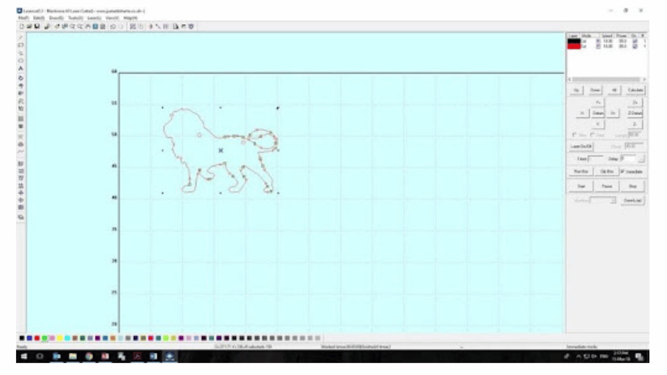
Step 5. Save as DXF File for Laser Cutter
Finally, in the “File” menu, choose the “Save As” option, and select “Desktop Cutting Plotter (AutoCAD DXF R14)(.dxf)” as the file format. Then, you can import the saved DXF file into laser cutting software for cutting or engraving production.
Final Words
The above are two methods for creating DXF file formats. It can be observed that using ZWCAD is much simpler. After completing your 2D drawing, you can directly export it as a DXF file without the need to switch to other tools. Additionally, you can also import other DXF files for browsing and editing. If you’re looking for an all-in-one solution, ZWCAD is the way to go. Hopefully, this article has been helpful to you.